A clear guide to M.2 keys (B, M, and B+M) and Socket 3 — what each notch means, which interface a socket actually carries, and how to match an SSD to the socket so it both fits and works, especially in industrial systems.
Key Takeaways
- A matching key does not guarantee the SSD will work. The key (B, M, or B+M) only controls whether the module fits. The socket must also be electrically wired for the SSD's interface: an M-keyed Socket 3 may be routed for PCIe NVMe only, SATA only, or both. A SATA M.2 SSD physically seated in a PCIe-only socket will not be detected.
- Socket 3 is the SSD socket — SATA or up to four PCIe lanes. Before specifying a drive, confirm three things against the motherboard documentation: key type, the interface the socket actually supports (SATA / PCIe / both), and the available PCIe lane count.
- Physical fit is more than the key. Module length (2280 / 2242 / 2230) must match the board's mounting standoff, and double-sided (D-type) modules plus any heatsink need vertical clearance — the constraint compact, sealed, or rugged industrial enclosures most often hit.
- Backward compatibility works, but it caps speed. A PCIe Gen4 SSD in a Gen3 x4 slot runs at Gen3; an x4 drive in a socket wired for only x2 runs at x2. Compatibility is preserved; the performance ceiling is the older or narrower link.
- Match the drive to what the socket is wired for — and on new designs, that increasingly means PCIe NVMe. Most current industrial boards wire Socket 3 for PCIe, so an M-keyed NVMe SSD is the default choice wherever the socket supports it. A B+M-keyed SATA module is still the right call when the socket is SATA-wired, or on long-lifecycle platforms whose BIOS boots only from SATA. B+M also gives the widest mechanical fit — it seats in either socket — but caps the link at PCIe x2 or SATA. Note that M.2 is neither hot-swappable nor hot-pluggable, and the host BIOS must support NVMe to boot from an NVMe drive.
Since its introduction in 2012, the M.2 (pronounced "M dot two") standard — formerly known as the Next Generation Form Factor (NGFF) and formally renamed to M.2 in 2013 — has become the dominant specification for internally mounted computer add-in cards. It gained widespread adoption primarily because it offered enhanced performance, greater application flexibility, versatility across multiple interfaces, and compact form factors. M.2 provides higher performance and capacity while minimizing module footprint.
Turbo-Boosting the Speed Shift: SATA to PCIe NVMe
Created to overcome the limitations of the SATA 6 Gb/s link and to provide more options for small form factor cards — including solid state drives (SSDs) in different sizes and with different capacities — M.2 supports both Serial ATA and PCIe interfaces, which allows SSD manufacturers to provide and customize more performance as well as cost options.
While M.2 continues to support SATA SSDs, the rise of applications requiring high responsiveness, faster data transfer speeds, low latency, and improved power efficiency has steadily increased the demand for PCIe M.2 SSDs. These SSDs leverage up to x4 PCIe lanes and the Non-Volatile Memory Express (NVMe) protocol, which deliver massive performance leaps over SATA SSDs.
The table below presents an overview of speed evolution from SATA to PCIe's latest iterations and their respective use cases.
| Interface | Max. Speed (2025) | Use Case | Reliability/Eccentricities |
|---|---|---|---|
| PCIe Gen6 x4 | 32,000 MB/s (theoretical) | R&D, next-gen servers | Engineering sampling, limited vendor support |
| PCIe Gen5 x4 | 16,000 MB/s | AI/analytics, high-performance computing (HPC) | Advanced supply, cooling a must |
| PCIe Gen4 x4 | 7,000 MB/s | Edge, databases, AI | Requires careful thermal design |
| PCIe Gen3 x4 | 3,500 MB/s | Legacy servers | Mature/stable, widely available |
| SATA | 600 MB/s | Legacy, rugged, field | Extreme longevity, broad vendor base |
PCIe 5.0 doubles PCIe 4.0's data transfer rates from 16 GT/s to 32 GT/s per lane. Its adoption is growing rapidly in professional, high-performance, and artificial intelligence and machine learning (AI/ML) sectors where its higher bandwidth can be leveraged. Users can expect blazing-fast application loading, data processing, boot times, and content production. M.2 supports current high-speed interfaces such as PCIe 5.0, with PCIe 6.0 emerging, alongside protocols like NVMe; it continues to support PCIe 4.0/3.0 and SATA for backward compatibility. This allows users to integrate new hardware with existing systems, though performance may be limited by the maximum speed of the older standard.
Sizes, Keys/Connectors, and Sockets: What the Nomenclature Means
M.2 modules come in different sizes and can also be utilized for wireless communication cards such as Wi-Fi® and Bluetooth® adapters. Other uses include near-field communication (NFC) modules, satellite navigation (GPS) modules, digital radio and WiGig wireless modules, and wireless wide area network (WWAN) modules for cellular network connectivity.
To ensure precise compatibility between different modules and motherboard sockets, the PCI Express M.2 Specification employs a standard naming convention.
M.2 Naming Nomenclature
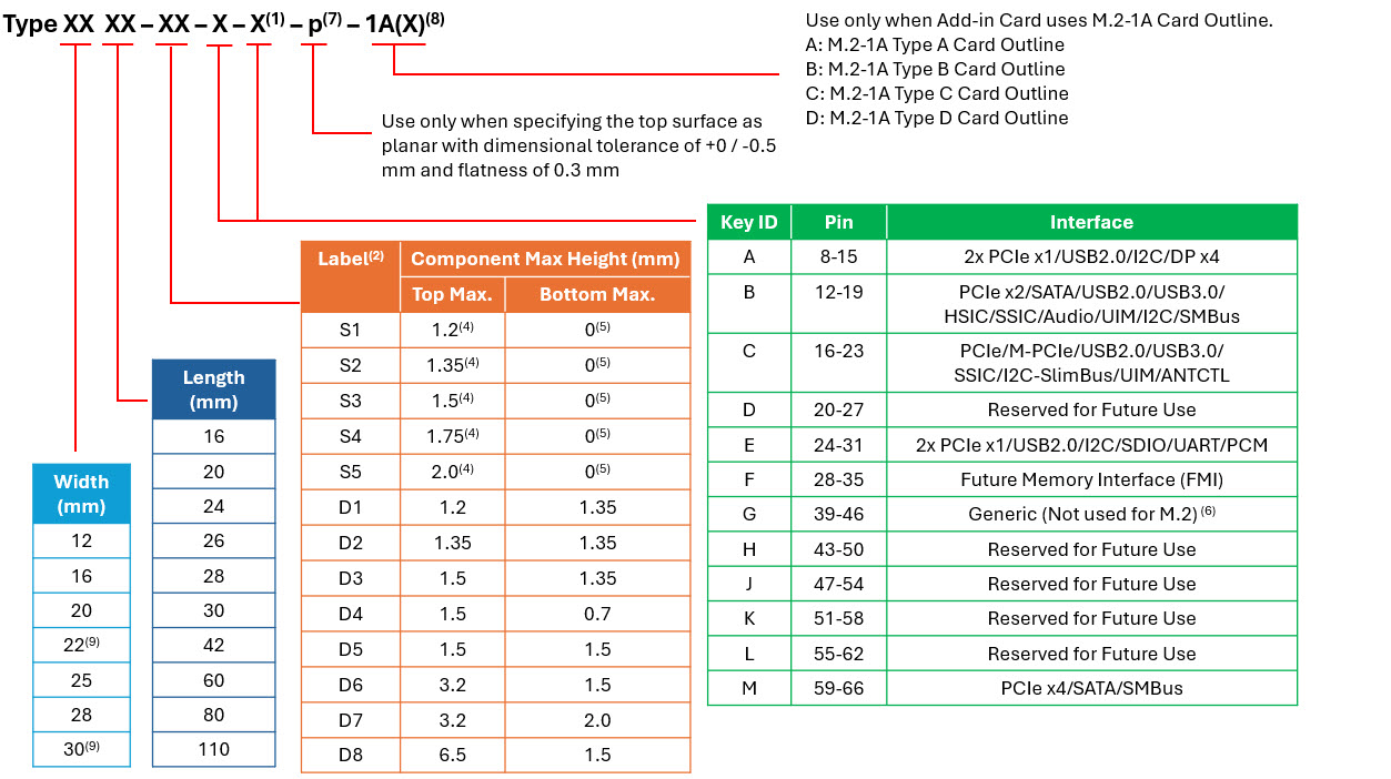
The following graphic provides details of the M.2 naming nomenclature in the PCI Express M.2 Specification Revision 5.1.
Notes:
- Use ONLY when a double slot is being specified.
- Label included in height dimension.
- This dimension is 11.5 mm but is written as 11 in Type name (i.e., BGA Type 1113).
- For BGA SSD, maximum height is measured with the solder balls collapsed and is valid whether the BGA is located directly on a platform or mounted on a module board.
- Insulating label allowed on connector-based design.
- Key G is intended for customer use. Devices with this key will not be M.2-compliant. To be used at customer's risk.
- Use only when specifying the top surface as planar.
- Use only when Add-in Card current consumption requirements exceed 0.5 A per pin (normal Power Rating) and/or card outline is changed to an M.2-1A type.
- M.2-1A only supports widths of 22 mm and 30 mm.
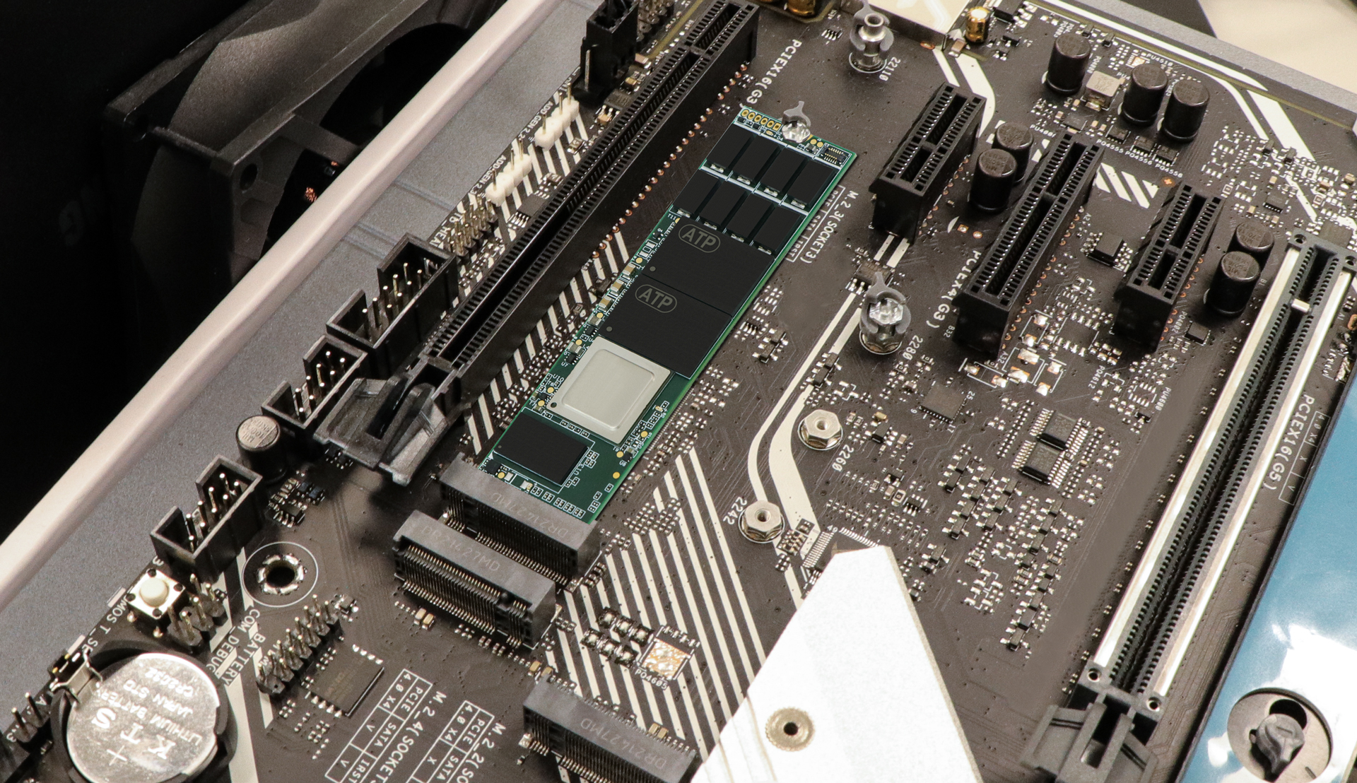
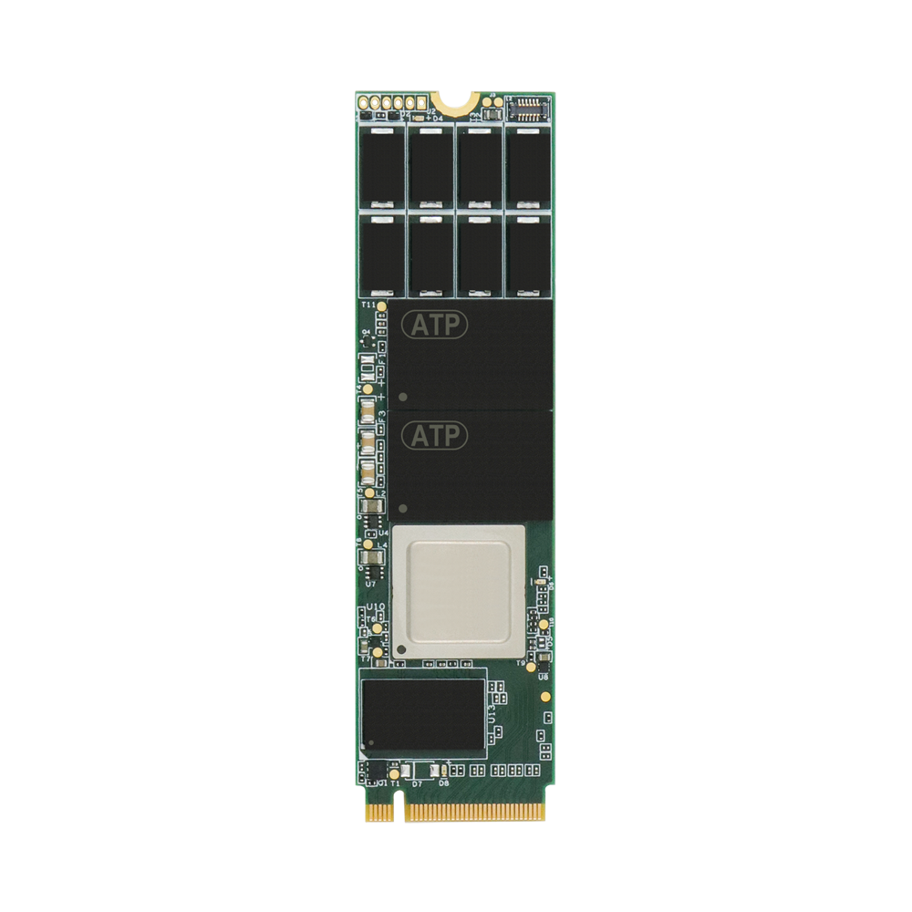
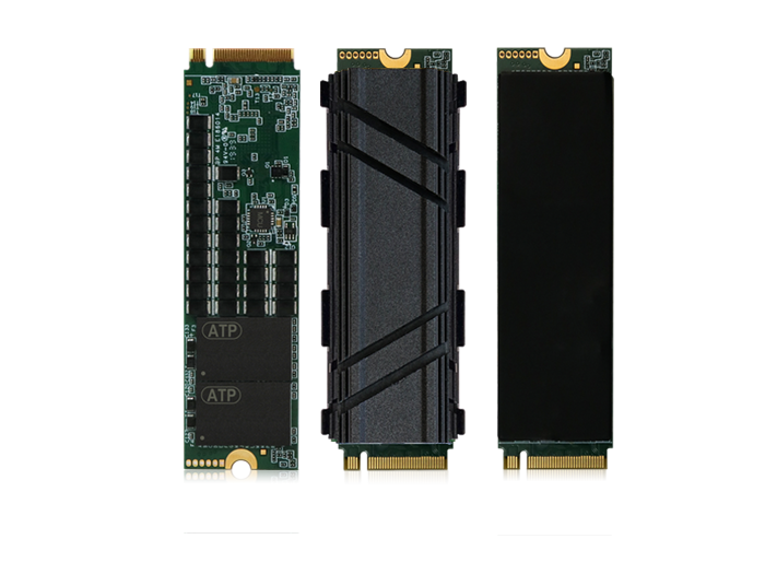
From the standard naming convention above, we can deduce the following information about this sample image, which shows an ATP PCIe® Gen4 NVMe M.2 2280-D2-M SSD:
Sockets
To ensure proper installation of M.2 modules, the M.2 standard in the PCI Express M.2 Specification has clearly distinguished "sockets" on the host. Each socket has a unique mechanical key, and modules are not interchangeable between sockets.
- Socket 1: connectivity socket for Wi-Fi®, Bluetooth®, NFC (near-field communication), or Wi-Gig.
- Socket 2: WWAN/SSD/Other socket that will support various WWAN+GNSS (global navigation satellite system) solutions, various SSD and SSD cache configurations, and other yet-undefined solutions. (If the motherboard has a Socket 2 for a WWAN card and it is not in use, the socket may accommodate a B+M-keyed small M.2 SSD. Please refer to your motherboard documentation for details.)
- Socket 3: SSD drive socket with SATA or up to four PCIe lanes.
Caution!
- Please refer to your motherboard documentation to make sure that your M.2 module fits and works with the corresponding socket on the motherboard.
- M.2 modules are neither hot-swappable nor hot-pluggable. Performing a hot-swap or hot-plug may damage the modules and cause harm to the person performing it.
Keys/Connectors
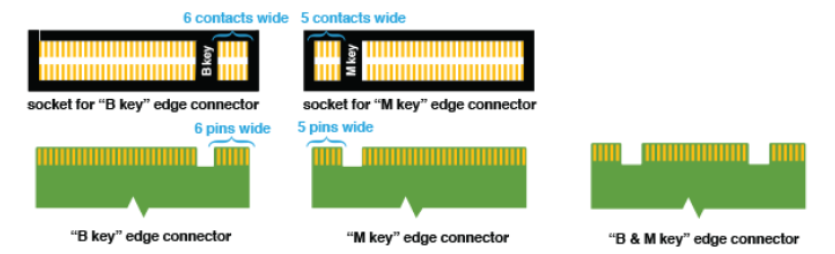
The edge connectors on the M.2 modules are also called "keys." They are used to prevent insertion into an incompatible socket on the host.
The M.2 specification identifies 12 key IDs on the module, but M.2 SSDs typically use three common keys: B, M, and B+M. You will find the key type labeled on or near the edge connector (or gold fingers) of the SSD.
The following table summarizes the key types typically used on M.2 SSDs, their physical characteristics (Key ID and notch position), typical use cases for ATP M.2 SSDs, main interface capabilities, PCIe lane counts, and common deployment scenarios.
| Key Type (Physical) | Key ID (Label) | Notch Position (Pin #) | ATP's Typical Use Cases (typical, not a spec) |
Main Interfaces | PCIe Lanes | Common Deployments (typical, not a spec) |
|---|---|---|---|---|---|---|
| B (single notch) | B | After pin 11 | Rugged/legacy builds | PCIe x2, SATA | Up to 2 | Gateways, field devices |
| M (single notch) | M | After pin 59 | High-performance SSDs | PCIe x4 | Up to 4 | Servers, analytics, edge |
| B+M (dual notch) | B+M | Both | Maximum compatibility | PCIe x2, SATA | Up to 2 | Fleet upgrades, spares |
B Key is often used in rugged or legacy devices requiring moderate bandwidth.
M Key is characteristic of high-performance SSDs designed for demanding servers, analytics systems, and edge computing.
B+M Key offers broader compatibility with devices accepting either key type, but is limited to PCIe x2 lanes or SATA speeds, thus offering moderate bandwidth.
To leverage higher PCIe interfaces like Gen4/Gen5, M-keyed SSDs can ensure maximum bandwidth with support for up to PCIe x4 interfaces, as well as better handling of the thermal envelope (the heat generated by blazing-fast, high-speed data transfers) through a combination of advanced hardware and firmware thermal management.
What Compatibility Issues Occur When Deploying SSDs in Industrial PCs?
SSD compatibility in an industrial PC breaks down into two separate questions that are easy to confuse: will the module fit, and will the host actually drive it? The M.2 key answers only the first. Six issues account for nearly every failed deployment:
- Key vs. socket mechanical mismatch. A module's key (B, M, or B+M) must match the socket's key, or it will not seat. An M-key SSD will not fit a B-key-only socket. B+M-keyed modules carry both notches and therefore fit either socket — which is why they are the most mechanically compatible, at the cost of being limited to PCIe x2 or SATA.
- Interface wired into the socket (the most common trap). Keying does not reveal what the socket is electrically connected to. An M-keyed Socket 3 can be routed for PCIe NVMe only, SATA only, or both. A SATA M.2 SSD will physically seat in a PCIe-only socket but will never be detected, and a PCIe NVMe drive will not work in a SATA-only socket. Always confirm the supported interface in the motherboard documentation, not just the key shape.
- PCIe lane count and generation. Socket 3 provides SATA or up to four PCIe lanes, but an individual industrial board may wire only two. An x4 drive runs in an x2-wired socket at x2, and a Gen4 SSD in a Gen3 slot negotiates down to Gen3. The link works; the bandwidth is capped at the lower of the two.
- Module length and mounting standoff. The board's standoff position fixes which lengths it accepts — 2280, 2242, or 2230. A 2280 drive cannot mount where only a 2242 standoff exists. Compact industrial boards frequently support the shorter lengths only.
- Vertical clearance for double-sided modules and heatsinks. Double-sided (D-type) modules place components on both faces, and heatsinks add height. Sealed, fanless, or rugged enclosures often lack the clearance for either, so a single-sided module — or a thinner copper-foil thermal solution — may be the only mechanically valid option.
- Firmware, boot, and serviceability. The host BIOS/UEFI must support NVMe to boot from an NVMe SSD; some long-lifecycle industrial platforms boot only from SATA. Finally, M.2 is neither hot-swappable nor hot-pluggable, so drives cannot be replaced on a live system — a real constraint for equipment that runs continuously.
For PCIe NVMe deployments where the socket and thermal budget allow it, ATP's Industrial PCIe® Gen4 NVMe M.2 SSDs are M-keyed for up to four PCIe lanes; where a socket is SATA-wired or maximum mechanical compatibility is the priority, a B+M-keyed SATA module is the safer specification.
ATP's M.2 Modules
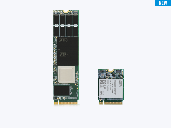
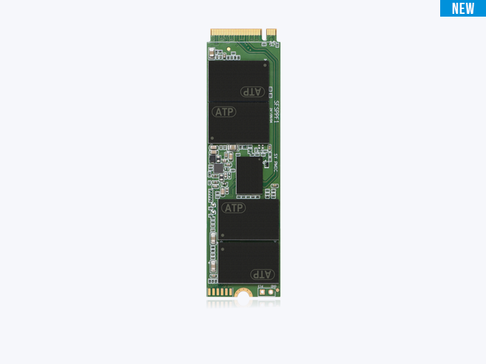
ATP's M.2 modules are available in the following form factors:
- Connectorized PCIe NVMe: M.2 2280 (PCIe Gen4 x4, M-keyed); M.2 2280, 2242, 2230 (PCIe Gen3 x4, M-keyed).
- SATA: M.2 2280, 2242 (SATA interface, B+M-keyed).
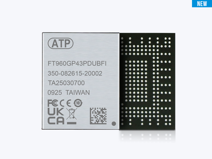
- Soldered down: PCIe M.2 Type 1620 HSBGA.
Labels: Single- or Double-Sided?
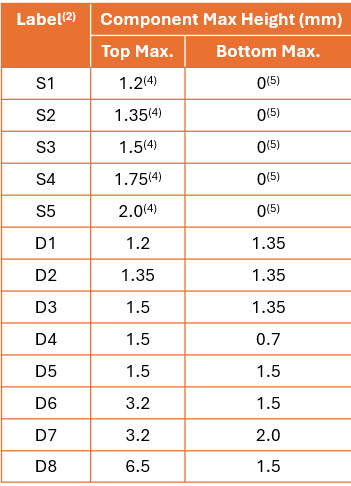
In the nomenclature table, the labels S1 to S5 and D1 to D8 indicate the maximum allowed component thickness and whether the module is single-sided or double-sided. When components are installed on only the top side of the module, they are "single-sided" (S1 to S5), while "double-sided" (D1 to D8) refers to modules installed with components on the top and bottom. Double-sided modules can accommodate more NAND chips to effectively expand capacity without altering the overall M.2 dimensions. The labels ensure compatibility with host devices that may have limited vertical clearance.
| SSD Type | Sides with Chips | Typical Max. Capacity | Clearance Needed |
|---|---|---|---|
| Single-sided | 1 (top) | 2–4 TB | Lower (easier fit) |
| Double-sided | 2 (top and bottom) | 4–8 TB+ | Higher (may need extra room) |
Keeping It Cool: Intelligent Thermal Management
M.2 SSDs, especially those supporting PCIe Gen4/Gen5, can achieve very high sequential read/write speeds, generating significant heat. If unmanaged, this could cause performance degradation and shorten the SSD lifespan.
The small form factor allows the integration of thermal solutions, such as specialized heatsinks that effectively dissipate heat away from the SSD's critical components like the controller and NAND chips. Double-sided modules maximize the surface area within tight spaces and allow the installation of more components while optimizing airflow within the system.
Firmware-based dynamic thermal management standardized under NVMe specifications, such as Host Controlled Thermal Management (HCTM), enables M.2 SSDs to monitor their temperature through SMART attributes and automatically adjust performance. This adaptive technology prevents overheating, balancing performance with thermal management, sustains peak performance in demanding tasks, and extends the SSD's lifespan.
When evaluating a heatsink, three criteria matter most:
- System, mechanical design, and performance criteria. Heatsinks must match the size and thickness of the M.2 SSD. Check whether the heatsink is designed for single- or double-sided modules, as height/vertical clearance within the host system is an important consideration. Airflow within the system, user applications, and workload/performance requirements must also be carefully considered.
- Material and design. Aluminum or copper? Finned or grooved? It is crucial to consider which options deliver improved thermal conductivity.
- Installation mechanism. How will the heatsink mount to the SSD? Common options include clips and screws. Choose a secure but gentle mounting that will not physically damage or pressure the SSD and its printed circuit board (PCB).
While heatsinks do not affect the electrical keying or socket interface of the M.2 SSD, some heatsink designs add physical height and bulk, which can interfere with adjacent motherboard components or cover the M.2 slots. Also, for extremely compact systems with strict space constraints, thicker or dual-sided heatsinks may obstruct the space around the socket area, limiting compatibility or installation. When choosing M.2 heatsinks, consider form factor compatibility, thermal efficiency, installation method, and device clearance.
ATP's Heat Dissipation Solutions: Thermal Joint Validation Service
ATP's heat dissipation solutions involve a continuous evaluation of our mechanical designs. This includes examining materials, appearance, airflow, and assembly processes to ensure optimal thermal management.
Thermal solutions experts at ATP know that one size does not fit all. Under the ATP Thermal Joint Validation Service, the unique thermal challenges for different use cases and scenarios are meticulously considered, and holistic as well as customizable solutions combining firmware and hardware technologies are offered to meet specific thermal requirements.
Below is a table detailing the solutions we offer for M.2 SSDs.
| Form Factor | HSBGA | M.2 2280 (Copper Foil) | M.2 2280 (4 mm Fin-Type) | M.2 2280 (8 mm Fin-Type) |
|---|---|---|---|---|
| Capacity | Up to 512 GB | Up to 1920 GB | Up to 1920 GB | Up to 1920 GB |
| Dimension: L x W x H (mm) | 16 x 20 x 1.6 | 80 x 22 x 3.9 | 80 x 24.4 x 8.3 | 80 x 24.4 x 12.3 |
| Material | Cu with Ni/Cr plating | Copper | Upper: aluminum alloy; bottom: stainless steel | Upper: aluminum alloy; bottom: stainless steel |
| Suitability | Limited space | Enough space for effective heat dissipation | Enough space for effective heat dissipation | Enough space for effective heat dissipation |
| Assembly | Molding | Adhesive | Clips design | Clips design |
Conclusion
Over a decade since it was first introduced, the M.2 standard continues to gain widespread adoption for enabling compact form factors, enhanced performance, and broad versatility — not only for SSDs but for other internally mounted computer add-in cards. Leveraging the latest high-speed PCIe interfaces, M.2 SSDs deliver data transfer speed enhancements over the previous generation while offering backward compatibility across different interface protocols and older generations, allowing users to integrate new hardware with existing systems.
The broad ecosystem of keys, sockets, and thermal solutions ensures that M.2 meets the evolving needs of present and future systems and applications. The decisive step in any deployment — especially in industrial PCs — is to match the drive not just to the key but to what the socket is actually wired for. For information and inquiries about ATP's M.2 SSDs, please visit the ATP website or contact an ATP representative in your area.
Frequently Asked Questions (FAQ)
Q1: What compatibility issues occur when deploying SSDs in industrial PCs?
A: Six issues account for most failures: key-vs-socket mechanical mismatch (B, M, or B+M must match); the interface the socket is actually wired for (an M-keyed socket may be PCIe-only, SATA-only, or both); PCIe lane count and generation, which cap speed when the host provides fewer lanes or an older generation; module length versus the board's mounting standoff (2280/2242/2230); vertical clearance for double-sided modules and heatsinks in compact enclosures; and BIOS support, since the host must support NVMe to boot from an NVMe drive. M.2 is also neither hot-swappable nor hot-pluggable.
Q2: Will any M.2 SSD fit any M.2 socket?
A: No. The edge-connector key prevents insertion into an incompatible socket: an M-key module will not seat in a B-key-only socket, and vice versa. B+M-keyed modules have both notches, so they fit either socket but are limited to PCIe x2 or SATA. Fitting is only half the requirement — the socket must also be electrically wired for the SSD's interface for the drive to be detected. For maximum mechanical compatibility, a B+M-keyed SATA M.2 SSD seats in either socket.
Q3: Does an M-keyed M.2 socket always support PCIe NVMe SSDs?
A: Not necessarily. The M key is a mechanical feature; it does not specify what the socket is wired to carry. An M-keyed Socket 3 may be routed for PCIe NVMe only, SATA only, or both, depending on the motherboard. A SATA M.2 SSD will physically seat in a PCIe-only M-keyed socket but will not be detected. Always confirm the supported interface in the motherboard documentation rather than inferring it from the key shape.
Q4: What is M.2 Socket 3?
A: Socket 3 is the M.2 SSD drive socket defined in the PCI Express M.2 Specification. It supports either SATA or up to four PCIe lanes and uses M keying. It is the socket type used for high-performance NVMe SSDs, distinct from Socket 1 (connectivity: Wi-Fi/Bluetooth/NFC) and Socket 2 (WWAN/SSD/cache). The actual interface and lane count a given Socket 3 provides depend on how the host wires it.
Q5: Why might a double-sided M.2 SSD not fit an industrial system?
A: Double-sided (D-type) modules carry components on both faces and need more vertical clearance than single-sided (S-type) modules, and any heatsink adds further height. Compact, fanless, or sealed rugged enclosures frequently lack that clearance, so the module or the lid can collide with adjacent components. Where space is tight, a single-sided module or a low-profile thermal solution such as copper foil is often the only mechanically valid choice. See ATP's work on NVMe thermal management for the trade-off between clearance and cooling.