The M.2 Standard: Past, Present, and Future
It has been 13 years since the M.2 (pronounced “M dot two”) standard was introduced in 2012. Formerly known as Next Generation Form Factor (NGFF), this specification for internally mounted computer add-in cards gained widespread adoption for high performance, compact size, interface versatility, and application flexibility. M.2 brings higher performance and capacity while minimizing module footprint for laptops, desktops, servers, and industrial systems.
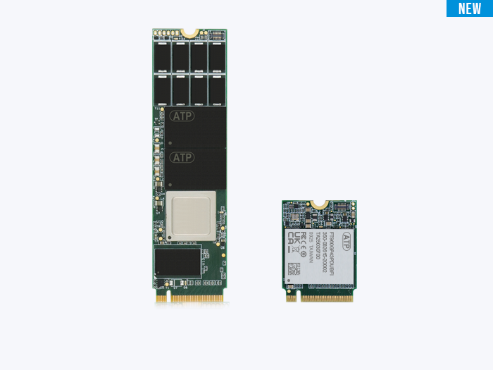
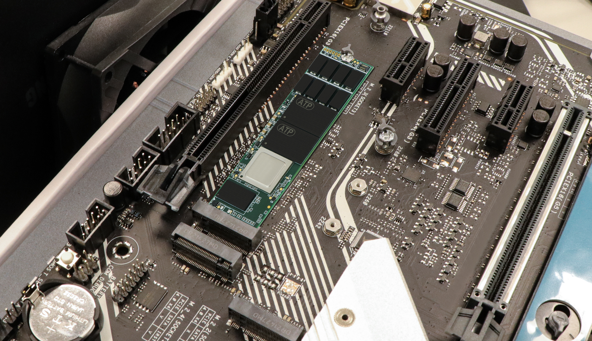 Figure 1. Example of M.2 card layout (source: ATP)
Turbo-Boosting the Speed Shift: SATA to PCIe NVMe
Created to overcome SATA 6 Gb/s limitations and support solid state drives (SSDs) in diverse sizes/capacities, M.2 accommodates both SATA and PCIe for flexible performance and cost options. PCIe M.2 SSDs, leveraging up to x4 PCIe lanes and NVMe, now far outpace SATA SSDs for speed, responsiveness, latency, and efficiency.
The table below presents an overview of speed evolution from SATA to the latest PCIe standards and their use cases.
| Interface | Max. Speed (2025) | Use Case | Notes |
|---|---|---|---|
| PCIe Gen6 x4 | 32,000 MB/s | R&D, Next-gen servers | Engineering sampling, limited vendor support |
| PCIe Gen5 x4 | 16,000 MB/s | AI/analytics, HPC | Advanced supply, cooling a must |
| PCIe Gen4 x4 | 7,000 MB/s | Edge, databases, AI | Requires careful thermal design |
| PCIe Gen3 x4 | 3,500 MB/s | Legacy servers | Mature, widely available |
| SATA | 600 MB/s | Legacy, rugged, field | Extreme longevity, broad vendor base |
Important: M.2 modules are not hot-swappable or hot-pluggable. Always power down before installing or removing!
Sizes, Keys/Connectors, and Sockets: What the Nomenclature Means
M.2 modules are used for SSDs and wireless adapters (Wi-Fi®, Bluetooth®, NFC, WWAN, etc.). The PCIe M.2 specification employs a standard naming convention for clear compatibility between modules and motherboard sockets.
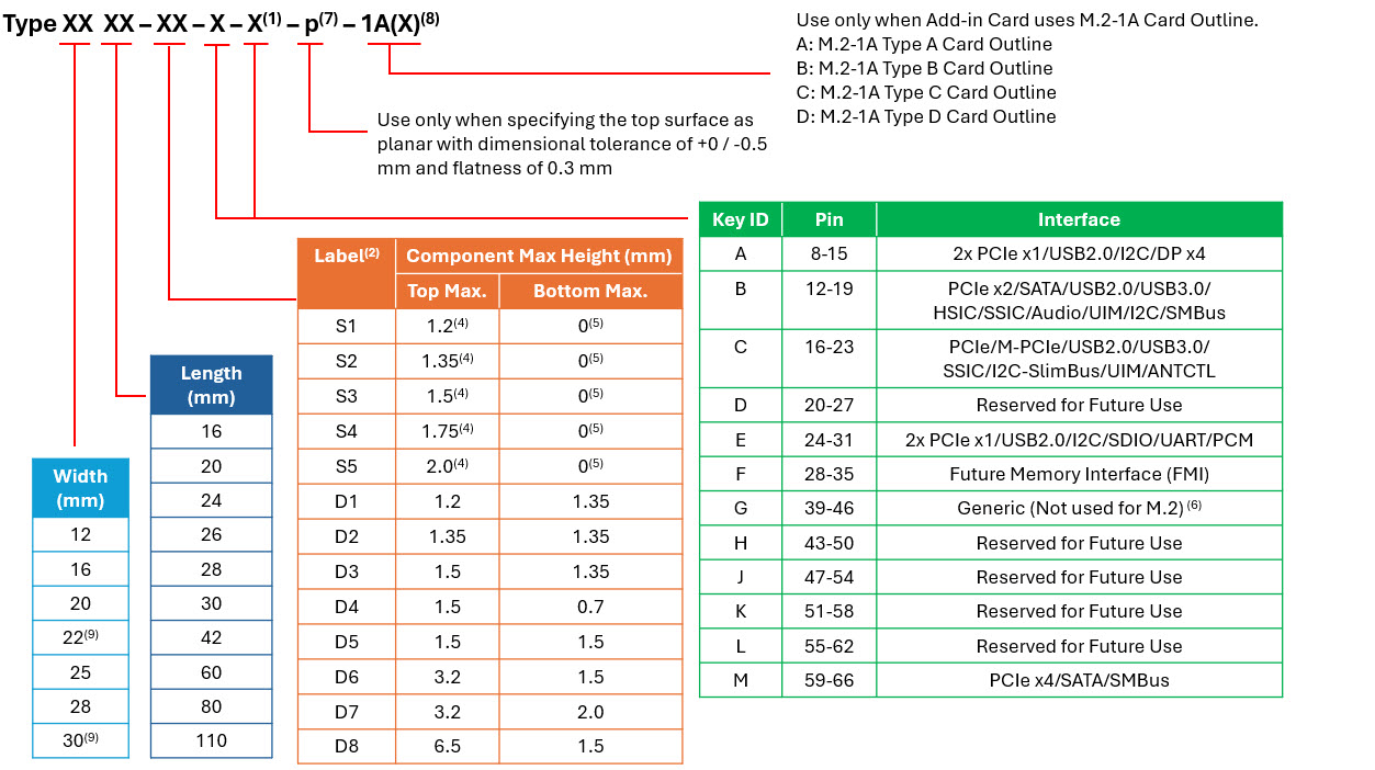 Figure 2. M.2 naming convention (PCI Express 5.1 Spec)
- Use ONLY when a double slot is being specified.
- Label included in height dimension.
- This dimension is 11.5 mm but is written as 11 in Type name (e.g., BGA Type 1113).
- For BGA SSD, max height is measured with solder balls collapsed (direct or module board mounting).
- Insulating label allowed on connector-based design.
- Key G is for customer use (not M.2-compliant).
- Use only if specifying top surface as planar.
- Use if Add-in Card current requirements exceed 0.5A/pin or card outline is M.2-1A.
- M.2-1A only supports widths of 22 mm and 30 mm.
M.2 Naming Example
 |
2280-D2-M Width: 22 mm Height: 80 mm D2 Label: Double-sided, max. height 1.35 mm/top and bottom Key ID: M (PCIe x4) |
Sockets
The specification defines three “sockets” with unique mechanical keys; modules are not interchangeable between socket types.
- Socket 1: Wi-Fi®, Bluetooth®, NFC, Wi-Gig modules
- Socket 2: WWAN, SSD/SSD Cache (may fit B+M-keyed SSDs—check docs)
- Socket 3: SSD Drive, SATA or up to four PCIe lanes
Never hot-swap or hot-plug M.2 modules.
Keys/Connectors
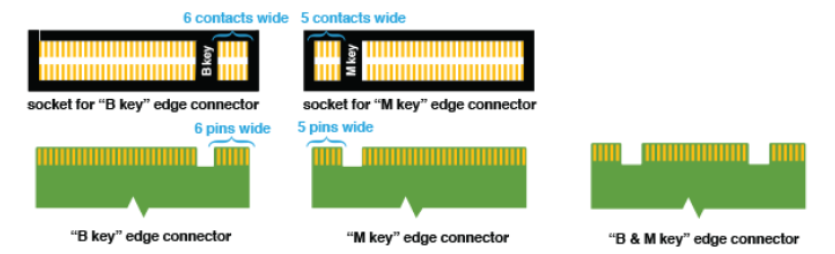 M.2 edge connector keys (Source: HowToGeek.com)
Edge connectors—“keys”—prevent incompatible insertion. M.2 SSDs use three main key types:
| Key Type | Physical (Notches) | Main Interface | PCIe Lanes | Use Case |
|---|---|---|---|---|
| B | Single notch (after pin 6) | PCIe x2, SATA | Up to 2 | Rugged/legacy builds |
| M | Single notch (after pin 59) | PCIe x4 (up to x8) | Up to 4/8 | High-performance SSDs |
| B+M | Dual-notch | PCIe x2, SATA | Up to 2 | Maximum compatibility |
B Key: For moderate bandwidth, rugged or legacy devices.
M Key: For high-performance SSDs and servers.
B+M Key: Broad compatibility, but limited to PCIe x2/SATA speeds.
ATP’s M.2 Modules
ATP’s M.2 modules are available in the following form factors:
| Type | Model / Interface | Notes |
|---|---|---|
| Connectorized | M.2 2280, PCIe Gen4 x4, M Key |
High-speed, high density for server/datacenter/enterprise |
| Connectorized | 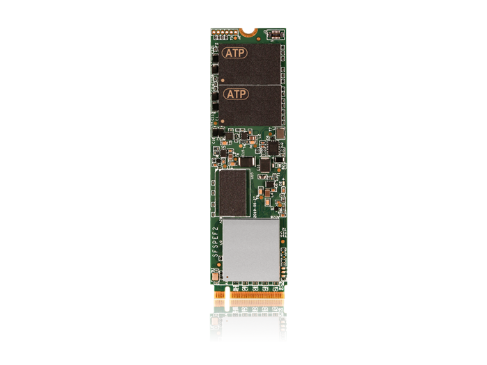 M.2 2242/2230/other, PCIe Gen3 x4, M Key |
Rugged/industrial/legacy/custom footprints |
| Connectorized | 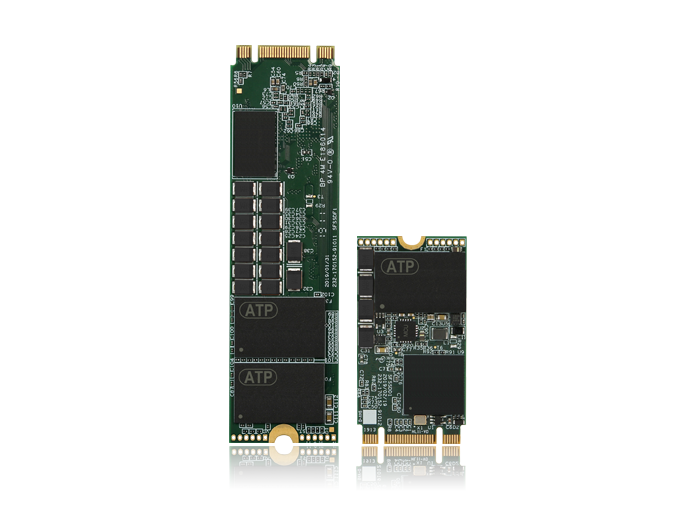 M.2 2280, 2242, SATA, B+M Keyed |
Legacy SATA compatibility, field and fleet upgrades |
| Soldered Down |  PCIe M.2 Type 1620 HSBGA |
Embedded, ultra-rugged form factors |
Labels: Single- or Double-Sided?
 Single- vs. Double-Sided M.2 SSD modules (Source: PCI Express Spec)
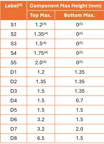
Nomenclature labels S1–S5 and D1–D8 indicate maximum component thickness and whether the module is single- or double-sided. Single-sided = components only on top; double-sided = chips on both top and bottom, for maximum capacity. Always check clearance in the host device.
| SSD Type | Sides with Chips | Typical Max. Capacity | Clearance Needed |
|---|---|---|---|
| Single-sided | 1 (top) | 2–4 TB | Lower (fits laptops, tablets, thin clients) |
| Double-sided | 2 (top & bottom) | 4–8 TB+ | Higher (for servers, industrial rigs) |
Keeping it Cool: Intelligent Thermal Management
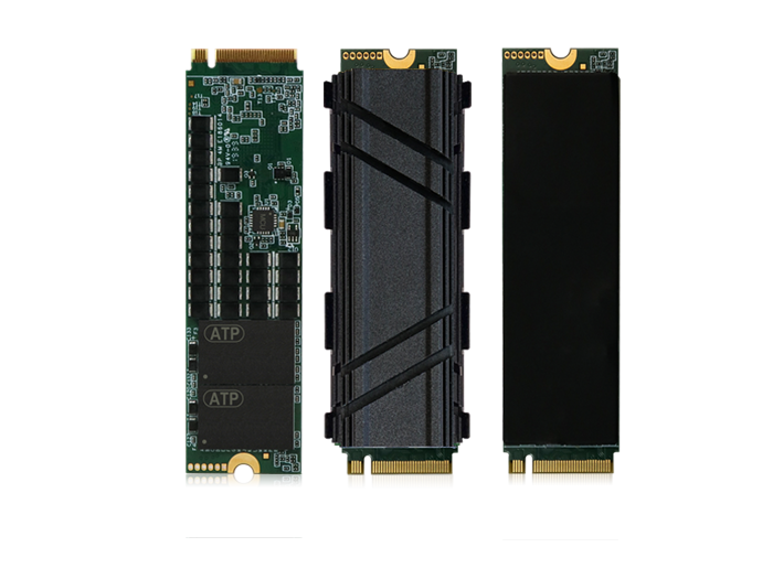 M.2 SSD with heatsink for advanced cooling
PCIe Gen4/Gen5 SSDs reach blazing speeds and generate significant heat. ATP integrates both hardware (heatsinks, copper/aluminum fin or groove designs) and firmware (Host Controlled Thermal Management) to maintain performance and SSD longevity. Modular heatsink solutions are tailored to fit single- or double-sided SSDs in all host devices.
- Fit: Heatsink height/thickness must match SSD/module/host clearance.
- Material: Select copper/aluminum, fin/grooved, clip-on/screw-down for best cooling and install safety.
- System airflow: Effective cooling depends on your host’s fans, vents, and usage pattern.
ATP Heat Dissipation Solutions (Thermal Joint Validation Service)
ATP's heat dissipation solutions include continuous evaluation of mechanical/firmware designs. The ATP Thermal Joint Validation Service ensures optimal thermal management for every application.
| Form Factor | HSBGA | M.2 2280 | |||
|---|---|---|---|---|---|
| Capacity | Up to 512 GB | Up to 1920 GB | |||
| Heatsink Type | Copper Heatsink | Copper Foil | 4mm Fin-Type | 8mm Fin-Type | 12mm Fin-Type |
| Material | Cu, Ni/Cr plating | Copper foil | Aluminum alloy (upper), stainless steel (bottom) | ||
| Suitability | Limited space | Plenty of room for effective dissipation | |||
| Assembly | Molding | Adhesive | Clips design | ||
Conclusion
Need more details? For technical or ATP product questions, contact ATP or visit our product pages.