Any power failure, no matter if it is just a glitch, a surge or a complete outage, can potentially damage a storage device and corrupt data unless there is an effective power loss protection (PLP) mechanism.
 As more and more solid state drives are being deployed in enterprise and industrial environments, an effective power failure protection technology must be in place to avert the damages that unexpected power interruptions could bring.
In a typical data center for example, hundreds of SSDs could be deployed. In the event of a power failure, drives can get corrupted, resulting in massive downtime as drives need to be reformatted and operating systems reinstalled; lost data could adversely impact business operations and affect customer relations; and, damaged drives will require replacements, translating to higher operating costs.
How Unsafe Shutdowns Affect an SSD
When the host wants to write data to an SSD, data is initially stored in a temporary buffer (volatile memory) if the SSD has a DRAM cache before being flushed to the non-volatile flash memory for safekeeping; otherwise, data is stored directly to the NAND flash (non-volatile memory) where it is stored safely even when power is terminated.
During a normal system shutdown, the host first alerts the SSD that the system is shutting down. The SSD then prepares for power removal, flushing data from volatile storage to non-volatile flash memory, and then signals the host that the drive is ready for power removal.
This process accomplishes two important things: First, it makes sure that data is safely stored before power is removed; and second, that mapping tables are updated. Mapping tables keep track of logical block addresses in relation to physical flash pages, pointing where data is stored on the flash drive.
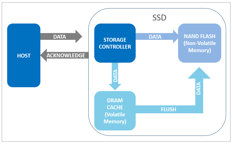
Figure 1. In a normal system shutdown, data is flushed to NAND flash memory and the SSD signals the host that the drive is ready for power removal.
An unsafe shutdown occurs when power is terminated before a shutdown notification is completed. This prevents data in the temporary buffers from being moved (“flushed”) onto the non-volatile NAND, causing data to be corrupted or lost, or rendering the storage device unusable. Examples of unsafe shutdowns include unexpected power outages, accidental removal of the SSD from the computer, unplugging the storage device while power is still on, or battery power loss.
SSDs are particularly vulnerable to power loss events. Unlike HDDs, SSDs do not have mechanical parts so every component is electronic. The internal data management of an SSD involves many operations happening in the background, and every power failure can mean undue interruption of those operations, which could affect drive performance.
Microcontrollers: Delivering Next-Generation Power Loss Protection
Power loss protection (PLP) mechanisms have been available on most SSDs, especially those designed for high-performance applications. Such industrial-grade storage devices are typically deployed extensively in harsh environments, operate 24/7, and require uncompromising device integrity.
Typical PLP solutions involve the use of batteries and super capacitors, which provide holdup power that allows the completion of controller and flash functions in the event of a power failure.
ATP Electronics, one of the first to design and release smaller form factor SSDs such as the M.2 2242 with an onboard PLP array, takes the notch higher by employing a microcontroller unit (MCU) that provides unparalleled defense for its next-generation Serial ATA and NVMe SSDs to deliver the best PLP protection in the industry.
How MCUs Enhance the PLP Mechanism
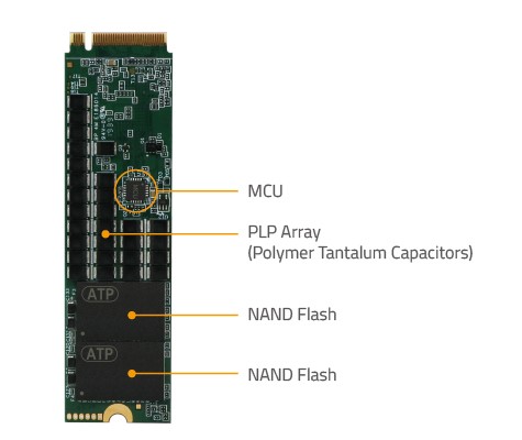
Integrated into ATP PowerProtector 4, the completely new design of the PLP array utilizes a new power management IC (PMIC) and new firmware‑programmable MCU that allow the PLP array to perform intelligently in various temperatures, power glitches and power states.
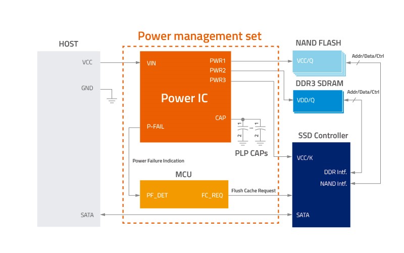
Figure 2. ATP’s new PLP array with PMIC and firmware-programmable MCU
- The MCU intelligently monitors de-glitch power failure conditions and checks the health status of capacitors through the I2C interface.
- Polymer tantalum capacitors provide sufficient sustaining power for data cache flushing if a surprise power loss condition occurs.
- The MCU can keep detecting power failure conditions; for example, for a 2.5” SSD, if input voltage drops down to less than 4.0 V for several consecutive milliseconds (de-glitch), the MCU will notify the controller to start cache flushing and at the same time, the capacitors will be activated to provide the sustaining power for cache flushing.
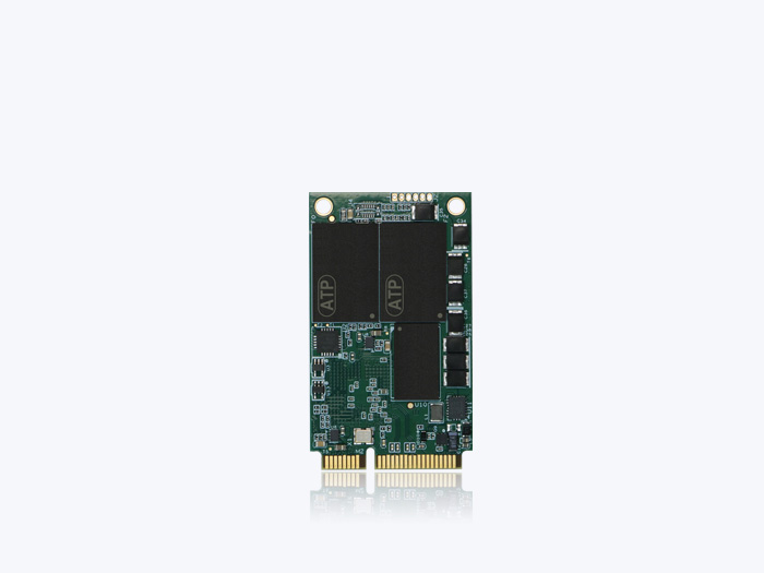
Figure 3. The MCU-based design implemented on the latest ATP NVMe SSD
Features and Benefits
- Over Input Voltage Protection. Input voltage refers to voltage supplied to the circuit. SSDs typically have a specific range within which input voltage may be tolerated — as an example, for ATP’s 2.5” SSDs, the upper limit is 16 V while for other SSD products, it’s 7 V. When the input voltage is higher than the specifications, it could cause irreversible damage to the components.
Next-generation ATP SSDs feature a switch between the external input voltage and the internal SSD circuit. This switch is controlled by the MCU. As input voltage is monitored by the MCU on real time, it protects the SSD by sending out a signal to the protection switch to cut off the input voltage once it is detected to be higher than the specified maximum tolerance rating.
- Power-up Inrush Current Suppression. Power-up inrush current refers to the high current drawn by a system at the moment it is turned on. This initial current, also known as switch-on surge or input surge current, is required to charge capacitors, inductors and transformers. When the power up inrush current is too high, it can cause damage to circuitry and components. The MCU-based design available on the latest ATP SATA and NVMe SSDs ensures that the inrush current does not exceed specified thresholds by enabling a soft start mechanism to minimize the impact of inrush current on the SSD.
- Input Power Noise De-glitch. Input power noise refers to a situation where the power source is unstable, causing unwanted periodic ripples and spikes.
The MCU helps with noise de-glitch through a judging mechanism that detects when power dips below a certain value, thus correctly identifying between a power loss or a simple power instability. Without the MCU, power instability may be misjudged as a power failure, and thus falsely trigger a cache flush and potentially lead the SSD to “hang” or freeze.
- Fast Power On-Off Control. Power on-off control refers to the mechanism that manages the timing between power off and the next power on. The MCU design can ensure faster and more efficient power on-off control.The following table illustrates the advantages of SSDs with MCU-based control compared with SSDs that do not:
Table 1. SSD power on-off with/without MCU
With MCU-based PLP, fast power on-off control can be guaranteed without potential risks of undetected drives due to the controller not being correctly reset.
- PLP Capacitors Over Voltage Protection
Polymer tantalum capacitors are important elements of ATP’s PLP technology. By providing holdup power, they ensure that data in the DRAM cache is flushed to NAND flash storage for safekeeping and the last write command is completed when a power loss event occurs.
Overcharging can damage the capacitors and thus compromise their protective function. The MCU monitors capacitor voltage in real time and disables charging once it detects that the voltage is too high. This guarantees that PLP capacitance is enough to complete cache flush during a power loss event. It also prevents the PLP capacitors from aging prematurely.
Summary & Conclusion
ATP PowerProtector 4 integrates the MCU-based design to deliver enhanced power management and PLP capabilities for ATP’s next-generation SATA and NVMe SSDs. By combining hardware and firmware solutions, the MCU-based design safeguards data as well as the storage device for higher levels of integrity and reliability. Depending on customer request, enhanced features may be customized, allowing PLP capabilities to be tailor-fitted according to unique requirements, application-specific needs or use cases.
The following table summarizes the benefits corresponding to each feature.
Table 2. Summary table shows how each MCU feature and benefit delivers enhanced PLP capability for ATP’s latest solid state drives and modules.
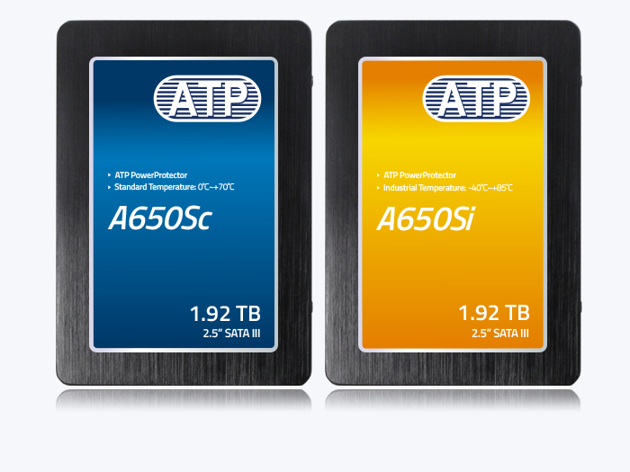
The next-generation ATP SSDs with the new MCU-based design include mSATA, 2.5” SSDs, M.2 2242/2280 and NVMe modules. Available with I-Temp and C-Temp support, the SSDs also feature RAID engine support and end-to-end data path protection. ATP’s “Industrial Only” solutions undergo stringent testing and validation to meet the high-reliability, high-performance and high-endurance requirements of mission-critical applications to deliver the best total cost of ownership (TCO) value. For more information on ATP's MCU-based industrial flash storage products, visit the ATP website or contact an ATP Representative.