Heat leaks charge out of worn NAND cells, so temperature — not just workload — sets how long an SSD can still return what was written to it. This article explains the retention mechanism, what JEDEC’s endurance standard requires after power-off, and which SSD architecture actually holds up in hot, fanless industrial systems.
Key Takeaways
- High-temperature capability is five design choices, not one rating. An SSD holds up in a hot industrial system because of the temperature grade of the product line, the NAND configuration behind its retention margin, the controller firmware that refreshes and recalibrates stored data, the physical path that carries heat off the controller and NAND, and how gracefully the drive throttles when it still gets hot. A drive can be rated −40°C to 85°C and still be the wrong architecture if the last three are missing.
- The rated temperature is a case temperature, not a room temperature. Operating temperature refers to the case temperature measured during device operation, and ATP qualifies its SSDs to case temperature (Tc). ATP puts Tc typically 10°C to 20°C above the ambient temperature (Ta) around the drive, so a fanless enclosure sitting at 70°C ambient can already put an 85°C-rated drive at its limit. Specify against the case temperature your enclosure actually produces.
- At temperature, data retention is the specification that moves — and NAND configuration is the lever. Retention figures are always quoted with a temperature: ATP publishes up to 10 years at 55°C for pSLC configurations. Fewer voltage states per cell means more margin against the charge loss that heat accelerates, which is why select ATP M.2 SSDs are rated at 100,000 P/E cycles in pSLC mode against 11,000 P/E cycles for native 3D TLC.
- Throttling converts a thermal problem into a performance cost — the question is how smoothly. On drives equipped with ATP’s Ace Thermal Throttling (AceTT), throttling begins when the SSD reaches or exceeds an 85°C threshold and steps performance down in up to 18 increments rather than the two or three stages typical of conventional implementations. Large-scale field research supports the mechanism: higher temperatures raise SSD failure rates, but drives that throttle show substantially lower failure rates at those temperatures.
- Wide temperature costs capacity, and sometimes you should not pay it. On ATP’s Gen4 NVMe M.2 line the 7,680 GB capacity is rated for commercial temperature operation only (0°C to 70°C), and some lines are specified −20°C to 75°C. If the cabinet is climate-controlled, the workload is light, and airflow is designed in, a commercial-temperature 3D TLC drive with a proper thermal solution is the correct specification — the industrial-temperature premium buys margin that system will never use.
How Does High Temperature Affect Data Retention?
Flash wear in solid state drives (SSDs) is commonly attributed to usage or workload, and endurance parameters are often expressed in program/erase (P/E) cycles. Another important, yet often-overlooked, factor in SSD endurance is operating temperature. While continuously operating at very high temperatures, the SSD can degrade quickly. A large-scale field study of flash memory failures across Facebook’s data centers found that higher operating temperatures correlate with higher SSD failure rates (Source: Meza, Wu, Kumar and Mutlu, “A Large-Scale Study of Flash Memory Failures in the Field,” SIGMETRICS 2015).
In settings where there could only be a handful of devices operating simultaneously for a number of hours at most, this heat issue may not be a big concern; but in environments like server farms where hundreds or thousands of devices are running at high speed and maximum performance 24/7, the temperature could go high enough to affect data retention. How can the integrity of data written on the flash drive be maintained at high operating or storage temperatures?
High-Temp Scenarios Affecting Data Retention
Prior to deployment, the SSD could lie dormant on a hot shelf for extended periods of time, causing concern that data or programs loaded before shipping will be lost. Heat accelerates charge loss from the cell, so the higher the storage temperature and the longer the drive sits, the more retention margin is consumed before the system is ever switched on. Unused SSDs are therefore best stored at low temperatures.
A related caution applies to the difference between the temperature at which data is written and the temperature at which it is read: a wide gap between the two raises the bit error rate, which is why ATP specifies a robust cross-temperature operating range and validates for it — see the cross-temperature testing described later in this article.
SSDs retain data by trapping and keeping electrons in the floating gate. Each cycle of electrons going in (programming) and out (erasing) wears out the tunnel oxide. While in use, SSDs subjected to high temperatures due to large workloads and poor thermal management can adversely impact data retention. Over time, when the tunnel oxide weakens, hot temperatures can cause electrons to leak out, resulting in higher bit errors. If there are too many bit errors, uncorrectable errors occur.
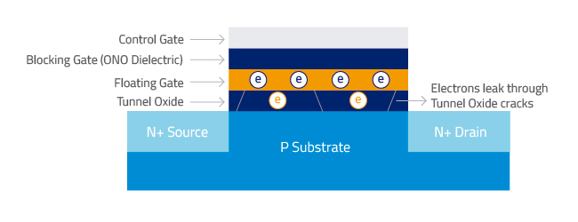
Similarly, SSDs that have been in active use for several years and then stored in high temperatures over long periods of time will have data retention issues.
The JESD218B.01 standard, released by JEDEC Solid State Technology Association, provides parameters for standardized endurance ratings, including retention requirements at certain temperatures. “This standard is based on use scenario where SSDs are actively used for some time, during which the SSDs are written to their endurance ratings, followed by a power-down time period in which data must be retained.” (Source: JESD218B.01. ©JEDEC Solid State Technology Association. 2016. For endurance workload definitions of Client and Enterprise Class SSDs, please refer to JEDEC JESD219A.)
- Client-Class SSDs typically used in a 40°C environment actively for 8-hour periods, must be able to retain data for 1 year in a temperature rating of 30°C after it is powered off.
- Enterprise-Class SSDs typically operating at 55°C for 24 hours a day should be able to retain data for 3 months at 40°C after it is powered off.
ATP Solutions for Better Endurance and Data Retention
ATP’s industrial temperature-rated flash storage products are specified to perform reliably across a wide temperature range of −40°C to 85°C. Read that range as what it is: operating temperature refers to the case temperature measured during device operation, and ATP qualifies its SSDs to case temperature (Tc) rather than to the ambient temperature (Ta) of the room. Because Tc typically runs 10°C to 20°C above the ambient around the drive, specify against the case temperature your own enclosure produces, not against the cabinet specification.
Endurance is likewise a configuration choice rather than a single number. Select ATP Gen4 NVMe M.2 SSDs are rated at 100,000 P/E cycles in pSLC mode against 11,000 P/E cycles for native 3D TLC, with a 150,000 P/E cycle configuration available on a project basis.
Meticulous Validation and Characterization
Stringent quality screening and characterization at IC level and package design validation ensure the reliability of the new die. Complete module functionality tests are performed at module level, while 100% diagnostic testing during pilot run confirms reliability at the mass production stage. That testing includes built-in self-test (BIST), wide temperature testing, and a complete drive test covering firmware, user and spare areas.
Thermal Sensors and Dynamic Thermal Throttling
Embedded SSD modules are designed for high-speed, superior performance in compact systems with space limitations. Slim and pint-sized yet power-packed with features and capabilities, embedded SSDs could be prone to thermal issues especially when operating under high workloads. ATP’s industrial-grade embedded SSDs are engineered for the toughest tasks under the most severe conditions.
To support outstanding performance and extended reliability in networking, enterprise, data center and other industrial applications, these rugged SSDs (select models) feature temperature sensors to detect the temperature of the device and the controller. If temperatures reach threshold levels, the Dynamic Thermal Throttling mechanism is activated to prevent the SSD from overheating, automatically adjusting SSD performance to cool it down.
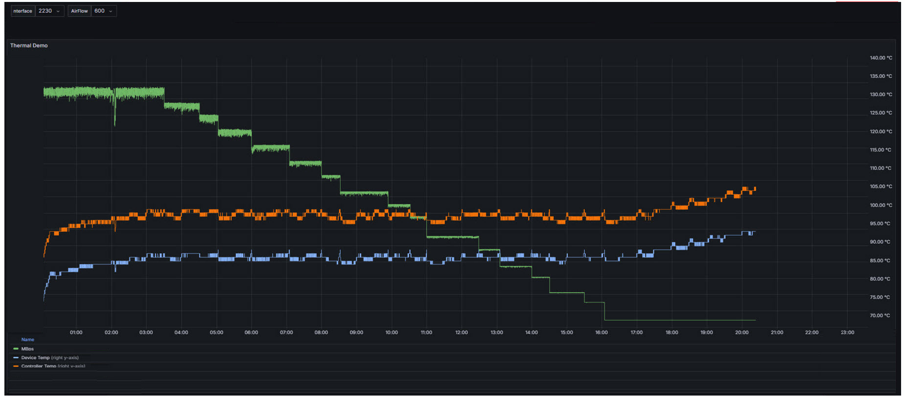
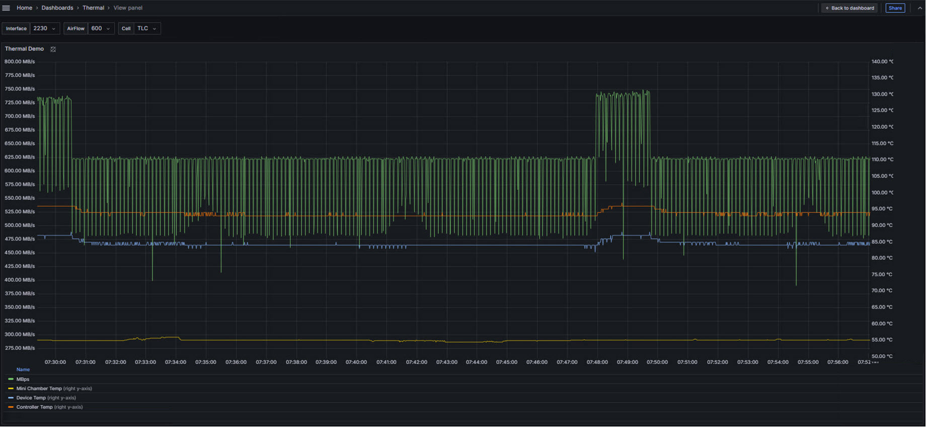
Dynamic thermal throttling reduces heat by trading throughput for temperature, and how finely it does so decides whether the drive settles or oscillates. Conventional implementations step performance down in only two or three stages, which produces abrupt drops and a drive that swings between full speed and a deep cut — in timing-sensitive systems, those swings are the problem rather than the heat itself. ATP’s current implementation, Ace Thermal Throttling (AceTT), begins when the SSD reaches or exceeds an 85°C threshold and steps performance down in up to 18 increments on drives equipped with it, tapering the drive toward thermal equilibrium instead of swinging through it.
Long Reliability Ratings
ATP’s industrial flash storage products are built to perform reliably over long periods of time. Mean Time Between Failures (MTBF) ratings run from over 2,000,000 to over 3,000,000 hours at 25°C depending on the product line — refer to the datasheet of the specific product for its rated value. Read the figure for what it is: MTBF describes the rate of random failures across a population of drives during their useful life at a stated temperature; it excludes wear-out and is not the service life of an individual drive. To project service life, work from the drive’s endurance rating — terabytes written (TBW) or drive writes per day (DWPD) — against the write volume you have measured. All products are designed, screened, tested and validated according to the strictest standards, from component to product level at ATP’s own manufacturing and validation facilities.
What SSD Architecture Works Best in High-Temperature Industrial Systems?
The architecture that holds up in a hot industrial system combines five things: an industrial-temperature product line qualified to a case temperature rather than an ambient one, a NAND configuration chosen for retention margin rather than capacity alone, controller firmware that actively refreshes and recalibrates stored data, a physical thermal path sized to the enclosure, and fine-grained thermal throttling as the last line of defense. No single one of these is sufficient. A drive carrying a −40°C to 85°C label but no thermal solution, no refresh mechanism and coarse two-stage throttling will disappoint in a sealed enclosure, and the specification sheet will not have warned you.
Start with the temperature grade — and read it as a case temperature
Industrial-temperature (I-Temp) parts are specified −40°C to 85°C and commercial-temperature (C-Temp) parts 0°C to 70°C, and the difference is decided at component selection and validation, not by a label. The specification detail that decides most designs, though, is which temperature is being rated. Operating temperature refers to the case temperature measured during device operation, and ATP qualifies its SSDs to case temperature (Tc) because ambient temperature (Ta) describes the room, not the thermal stress on the drive. ATP puts case temperature typically 10°C to 20°C above the ambient around it — so an enclosure holding 70°C of ambient air can already be presenting an 85°C case to the drive, and a drive qualified at Ta rather than Tc has quietly borrowed that margin from you.
Two consequences follow for specification. First, get the case temperature of your own design measured on the drive once the system has reached thermal steady state under its real workload, and specify against that number. Second, ask any supplier which temperature their range refers to, and treat a range with no Tc/Ta declaration as unqualified.
NAND configuration: what actually buys retention margin at temperature
Temperature attacks stored data through the mechanism described earlier in this article — a weakened tunnel oxide lets electrons leak from the floating gate, bit errors climb, and eventually errors become uncorrectable. The architectural counter is to leave more voltage margin between the states a cell has to distinguish. That is what pSLC mode does: it configures 3D TLC NAND to store one bit per cell instead of three, trading roughly two-thirds of the capacity for margin. The published figures show the size of the trade — select ATP Gen4 NVMe M.2 SSDs are rated at 100,000 P/E cycles in pSLC mode against 11,000 P/E cycles for native 3D TLC, with a 150,000 P/E cycle configuration available on a project basis, and ATP’s published data retention figure — up to 10 years at 55°C — is annotated for pSLC. Note that the retention figure carries a temperature at all: that annotation is the specification telling you retention is a function of heat.
Where the write volume is genuinely low, this is a trade worth refusing. A gateway writing a few hundred megabytes a day does not need 100,000 P/E cycles, and giving up two-thirds of the capacity to get them is a poor use of the budget. In that case, spend on the thermal path and the refresh firmware instead — the parts of the architecture that address heat directly.
Controller and firmware: the layer that keeps data readable as it heats
The controller is where a high-temperature architecture is actually built, because heat produces a rising bit error rate long before it produces a failure. Four capabilities matter, and they are worth confirming line by line against the product you are specifying:
- Strong error correction. LDPC (Low-Density Parity Check) ECC corrects a higher raw bit error rate than the BCH engines it replaced — which is what a hot drive with a worn tunnel oxide produces.
- Proactive data refresh. On drives that offer them, ATP AutoRefresh monitors error-bit level and read counts and relocates data out of an affected block before a threshold is reached, and Dynamic Data Refresh scans the user area while the drive is free of host commands. Both address stored data that is degrading in place — the exact failure mode heat accelerates.
- Read calibration. On drives that offer it, Auto-Read Calibration adjusts read voltage thresholds as cell characteristics shift, which is what allows data written at one temperature to be read reliably at another.
- Cross-temperature validation. ATP validates the case that catches out drives qualified only at a steady temperature: writing at 85°C and reading at −40°C, and writing at −40°C and reading at around 85°C, using read-retry techniques and comparison against the original data pattern. Four-corner testing extends the same idea across the maximum and minimum of both operating temperature and input voltage.
Sensor placement belongs in this layer too. Controller, NAND and other components have different thermal thresholds, and a sensor placed far from the hot component under-reports — which means throttling engages late, or not at all, on a drive that is already too hot.
The thermal path: form factor, heat spreader and airflow
Firmware can only manage heat it can get rid of. NVMe drives concentrate the problem because, as ATP has documented, their high transfer speeds and power consumption generate more heat precisely in the compact, fanless enclosures where they are most often installed — and multiple die stacked per IC and dense double-sided PCB layouts add to it. The architectural choices are physical:
- Form factor as a heat path. A high-density NVMe U.2 SSD can carry a thermal pad over the controller and NAND area that dissipates heat through the aluminum housing; an M.2 module is a bare board until you add something to it.
- Heat spreader and heatsink options. ATP’s M.2 thermal options include a nickel-coated copper heat spreader on the controller and 4 mm or 8 mm fin-type heatsink designs, with copper foil available where vertical clearance is the binding constraint.
- Interface, chosen against the thermal budget. Where an enclosure cannot remove heat and the workload does not need Gen4 bandwidth, a lower-power SATA drive is a legitimate architectural answer to a thermal problem — the fastest interface is not the right one if the system cannot cool it.
- Airflow, stated in numbers. Airflow is specified in linear feet per minute (LFM), and it changes what the rest of the architecture has to absorb.
ATP’s thermal management assessment starts from the system profile rather than the drive. These are the scenarios it works from:
| Application profile | Ambient condition | Airflow | What the criterion implies for the architecture |
|---|---|---|---|
| Fanless server system | ~60°C | No airflow | Operate under 60°C without reliability concerns — conduction path and refresh firmware carry the design |
| Fanless box PC | ~70°C | No airflow | Stay operational without shutting down at a low performance requirement — graceful throttling matters more than peak throughput |
| Data logger | ~85°C | 1,200–1,800 LFM | Sustained read/write performance at Ta = 85°C — the hardest case: I-Temp line, heatsink and fine-grained throttling together |
| IIoT server | ~55°C | Min. 2,000 LFM | Fan action triggered by composite temperature must stay in range — the drive’s reported temperature drives system-level behavior, so sensor accuracy is the specification |
Scenario criteria as published in ATP’s thermal management assessment; the architecture implications in the last column are this article’s reading of them.
Read the second and third rows together and the design rule falls out: the same 85°C figure means something completely different with 1,500 LFM behind it than it does in a sealed box. Airflow, not the rating on the label, decides which architecture you need.
Throttling behavior: what happens when the design still runs hot
Thermal throttling is a protective mechanism that reduces drive speed to bring temperature down, and every architecture eventually relies on it. What separates implementations is granularity. Conventional solutions adjust performance in only two or three stages, which produces abrupt drops and a drive that oscillates between full speed and a deep cut — and in timing-sensitive systems those swings are the problem, not the heat. On drives equipped with ATP’s Ace Thermal Throttling (AceTT), throttling begins when the SSD reaches or exceeds the 85°C threshold and steps down in up to 18 increments, holding the drive at thermal equilibrium instead of swinging through it. In ATP’s chamber testing, a drive operating in TLC mode under an emulated 55°C ambient reached a device temperature near the 85°C range and settled into steady-state operation there — a useful illustration of how far a sustained NVMe workload can push case temperature above the air around it.
There is independent support for building around throttling rather than treating it as a failure. The large-scale field study of flash reliability at Facebook (Meza, Wu, Kumar and Mutlu, SIGMETRICS 2015) found that higher operating temperatures correlate with higher SSD failure rates — but that drives employing throttling showed substantially lower failure rates at those temperatures than drives that did not. Throttling is not a workaround for a hot design; it is part of what makes a hot design survivable.
The honest tradeoff: throttling protects the flash by slowing the drive down. If the application has a hard latency or sustained-throughput budget, the correct response is to fix the thermal path so the drive rarely reaches the threshold — not to select a drive that throttles more politely.
A specification sequence that works
- Measure, don’t assume. Record case temperature on the drive at thermal steady state under the real workload, and record the airflow in LFM. Everything else follows from these two numbers.
- Pick the temperature grade from the measured case temperature, not from the ambient specification of the cabinet, and confirm the supplier’s range is a Tc range.
- Pick the NAND configuration from the write volume, then check the retention requirement against the published retention-at-temperature figure for that configuration.
- Confirm the firmware layer line by line — LDPC ECC, refresh and read-calibration features, cross-temperature validation — because these vary by product line and are what keep data readable as the drive ages hot.
- Size the thermal path last, against the clearance you actually have: heat spreader, fin height, or copper foil where a double-sided module and an enclosure lid are already competing for the same millimetres.
Where the enclosure is climate-controlled and the workload is light, this sequence should land on a commercial-temperature 3D TLC drive with a designed-in thermal solution, and that is the right answer. The industrial-temperature, pSLC, heatsinked configuration earns its cost in the cases the sequence identifies: sealed or fanless enclosures, sustained write workloads, and deployments where nobody will be visiting the site to replace a drive.
Conclusion
As more and more organizations increasingly adopt SSDs as the storage of choice, they also seek more cost-effective ways to balance performance and cost. Many have turned to flash technologies that are capable of higher densities but often face performance, reliability and endurance challenges and are typically unable to handle extreme temperatures.
ATP industrial SSDs are built to endure long years of dependable use and retain data even under tough operating conditions, workloads and temperatures. For detailed information on ATP’s industrial temperature solutions, visit the ATP website or https://global.atpinc.com/ or contact an ATP Representative or Distributor in your area.
Frequently Asked Questions (FAQ)
Q1: What SSD architecture works best in high-temperature industrial systems?
A: The architecture that works best combines an industrial-temperature product line qualified to case temperature, a NAND configuration chosen for retention margin, controller firmware that refreshes and recalibrates stored data, a physical thermal path sized to the enclosure, and fine-grained thermal throttling. In practice that means an I-Temp (−40°C to 85°C) line rather than a C-Temp (0°C to 70°C) one; pSLC configuration where the write volume or the retention requirement justifies giving up roughly two-thirds of the capacity; LDPC error correction with proactive data refresh and read calibration on drives that offer them; a heat spreader, fin-type heatsink or conductive housing to move heat off the controller and NAND; and throttling that steps down gradually rather than in two or three abrupt stages. The temperature rating alone does not describe an architecture — two drives with the same −40°C to 85°C label can behave completely differently in a sealed enclosure.
Q2: How much hotter is an SSD’s case temperature than the ambient temperature around it?
A: Case temperature is typically 10°C to 20°C higher than the ambient temperature around the drive, and the gap widens with sustained workloads and restricted airflow. Operating temperature refers to the case temperature measured during device operation, and ATP qualifies its SSDs to case temperature (Tc) rather than ambient (Ta) for exactly this reason: ambient describes the environment, not the thermal stress on the device. The practical consequence is that a fanless enclosure holding 70°C of ambient air can put an 85°C-rated drive at its rated limit, and a high-speed NVMe drive under a sustained workload can exceed even that gap — in ATP chamber testing that emulated a 55°C ambient, device temperature reached the 85°C range. Measure case temperature on the drive itself after the system reaches thermal steady state under its real workload rather than working from the cabinet specification.
Q3: Does an industrial SSD need a heatsink in a fanless enclosure?
A: It depends on the interface and the workload, not on whether the enclosure has a fan: high-speed PCIe NVMe drives under sustained write loads usually do, and low-power SATA drives under light workloads often do not. NVMe drives generate more heat because of their higher transfer speeds and power consumption, and they are most often installed in exactly the compact, fanless systems that cannot remove it, so ATP offers thermal options including a nickel-coated copper heat spreader on the controller and 4 mm or 8 mm fin-type heatsinks, with copper foil where vertical clearance is limited. Two design cautions apply before specifying one: a fin-type heatsink adds height that a sealed or low-profile enclosure may not have, particularly with a double-sided module; and where the workload does not need Gen4 bandwidth, selecting a lower-power SATA drive can be a more effective answer to the thermal problem than cooling a faster one.
Q4: Does pSLC improve data retention at high temperature, or only endurance?
A: It improves both, because the mechanism behind each is the same voltage margin. pSLC mode configures 3D TLC NAND to store one bit per cell instead of three, so the controller distinguishes two voltage states instead of eight — leaving far more margin against the charge loss that heat accelerates as the tunnel oxide weakens. That shows up in both specifications: select ATP M.2 SSDs are rated at 100,000 P/E cycles in pSLC mode against 11,000 P/E cycles for native 3D TLC, and ATP’s published data retention figure of up to 10 years at 55°C is annotated for pSLC configurations. The cost is capacity — roughly two-thirds of it — so pSLC is the right call for write-intensive or long-retention roles in hot environments, and the wrong call for a lightly written system where the budget is better spent on the thermal path and the refresh firmware.
Q5: How is an industrial SSD validated for high-temperature and cross-temperature operation?
A: Beyond operating at a steady high temperature, an industrial SSD is validated across temperature transitions, because data written at one temperature and read at another is where marginal drives fail. ATP runs cross-temperature testing in both directions — writing at 85°C and reading at −40°C, and writing at −40°C and reading at around 85°C — using read-retry techniques and comparing the result against the original data pattern, with bit error rate analyzed to assess NAND robustness. Four-corner testing extends this to the maximum and minimum of both operating temperature and input voltage over repeated cycles, and 100% diagnostic testing during pilot run adds built-in self-test, wide-temperature testing and a complete drive test covering firmware, user and spare areas. When comparing suppliers, ask which of these are run on the specific product line rather than on the platform generally — that answer, not the temperature range printed on the datasheet, is what distinguishes an industrial drive from a commercial one with a wider label.